
WebGL is a JavaScript API used to render 2D and 3D interactive graphics directly within a web browser. I have built an optimized framework with WebGL that supports transformations, lighting, texture mapping, and more. By utilizing WebGL to interface with the OpenGL ES Shading Language (similar C/C++ and made for graphics programming) and JavaScript for core logic, the framework achieves high performance and flexibility in rendering real-time graphics.
LIVE DEMOFeatures at a Glance:
- Algorithmically generated primitives
- Spheres, Cylinders, and Cubes are generated algorithmically.
- Each vertex stores information about position, color, normal, and texture coordinates (if applicable).
- 3D transformations
- Full support for real-time 3D rotation, translation, and scaling of any object.
- Camera
- Complete implementation of the transformation pipeline.
- Objects start in local space and are transformed until reaching screen space.
- Lighting
- Support for ambient, diffuse, and specular lighting.
- Phong shading is used for realistic lighting effects.
- Texture mapping
- Support for applying 2D textures on 3D objects.
- Environment cube mapping (reflective surfaces)
- Support for skyboxes.
- Support for real-time reflections on 3D objects.
Primitives
Info
- Spheres, Cylinders, and Cubes are generated algorithmically.
- Each vertex stores information about position, color, normal, and texture coordinates (if applicable).
Cubes, Cylinders, and Spheres are generated algorithmically. They can be generated in their normal form or or be scaled, rotated, and translated into the desired position.

At runtime, each vertex position is calculated and loaded into a vertex buffer object (VBO) to be read and processed by WebGL. The order in which the vertices are connected when rendered is stored in the index buffer (this stores the index of each vertex in the position array, rather than the entire vertex, for better efficiency). Vertex color, normal, and texture coordinate are also calculated and stored.

Vertices are connected to their neighbors in the VBO to create more advanced renderings. By default, the program renders vertices as triangles. These triangles are calculated by grouping 3 consecutive vertices from the index buffer. For example, [V1, V2, V3, V4, V5, V6] would be grouped into (V1, V2, V3), (V4, V5, V6) to create the triangles. The primitives below are rendered using a triangle fan to better visualize the connections.

3D Transformations
Info
- Full support for real-time 3D rotation, translation, and scaling of any object.
WebGL uses a right-handed coordinate system. This means that:
- The X axis points to the right
- The Y axis points up
- The Z axis points out of the screen, towards the viewer
3D transformations are represented using a homogeneous coordinate system. This adds an additional coordinate (w) to each point that is represented. Because of this, we are able to combine multiple transformations into a single matrix. For example, a single matrix can be used to compose separate transformations, such as rotating, scaling, and translating a point, into a single matrix.
The order in which each transformation matrix is multiplied with the other to create one single matrix depends on if the operation is occurring in local space or global space. For global transformations, pre-multiply the matrices (multiply in reverse order). For example, take the point (2, 2, 2). Suppose we want to transform this point by:
- Translating it (5, 5, 5)
- Rotating it 45 degrees about the Z axis
- Scaling it by 0.5
This will occur in global space. Because we are in a right-handed coordinate system, the rotation will appear counter clockwise. The transformation matrix would look like this:
Now, we can apply this combined transformation matrix onto our point (2, 2, 2).
By using homogeneous coordinates we are able to combine the 3 separate transformations into a single matrix. When transforming large geometry with many vertices, only needing a single matrix saves significant resources by reducing the amount of matrix multiplication needed.
Camera
Info
- Complete implementation of the transformation pipeline.
- Objects start in local space and are transformed until reaching screen space.
When viewing objects in 2D, the objects exist in Local Space, then are transformed to World Space, the finally are mapped onto the viewport in Screen Space. Viewing objects in 3D adds two more transformation spaces: Eye Space (which orients objects relative to the camera) and Clip Space (which determine which parts of the scene are visible, or which parts of the scene “clip” others).
- Local (Object) Space
- Modeling Transformation
- World Space
- Viewing Transformation
- Eye Space
- Projection Transformation
- Clip Space
- Perspective Divide
- Normalized Device Coordinate Space
- Viewport Mapping
- Screen Space
Eye Space and Viewing Transformation
To move from local to eye space, the Model View Matrix is used. This is a composition of the:
- Model Transformation Matrix (see above) which transforms geometry from local to world space and is specific to each piece of geometry in the scene.
- View Transformation Matrix which transforms geometry from world space to eye space and is usually shared by all objects in the scene.
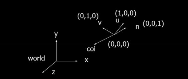
Eye space uses a separate coordinate frame that is bound to the orientation of the camera. This coordinate frame is located at the camera’s position and is aligned with its orientation. It consists of several components:
- The Center of Interest (COI): is where the camera is looking at.
- The Normal Vector from the top of the camera defines which direction is “up” from the camera’s orientation. It will reflect any changes such as the camera tilting or rolling.
- The Up Vector (v) is the vertical axis in the camera’s local space. It defines what is “up” relative to the camera. It is orthogonal to the u-axis and n-axis, so it may not always be aligned with the camera’s normal vector.
- The View Vector (n) aligns with the camera’s line of sight, towards the COI.
- The Right Vector (u) is the cross product: u = v x n
The view matrix is an encoding of the camera’s position along with (u, v, n). When the view matrix is multiplied with the modeling matrix, the result is the Modelview Matrix.
When multiplying the modelview matrix to an piece of geometry’s vertices, the geometry is transformed from local space to eye space.
Clip Space and Projection Transformation
Projection Transformation maps geometry from 3D space onto a 2D screen. There are two types:
- Perspective Projection maps geometry similar to how it would appear in real life in a picture. Objects that are further away from the camera are smaller.
- Orthographic (Parallel) Projection maps geometry to a plane using parallel lines. Objects remain the same size, regardless of distance from the camera.
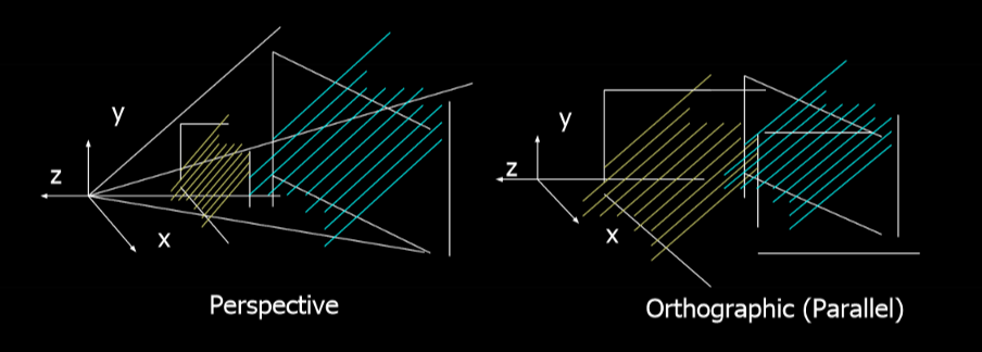
Below is an oversimplification of perspective projection, which is the projection type used in this engine.
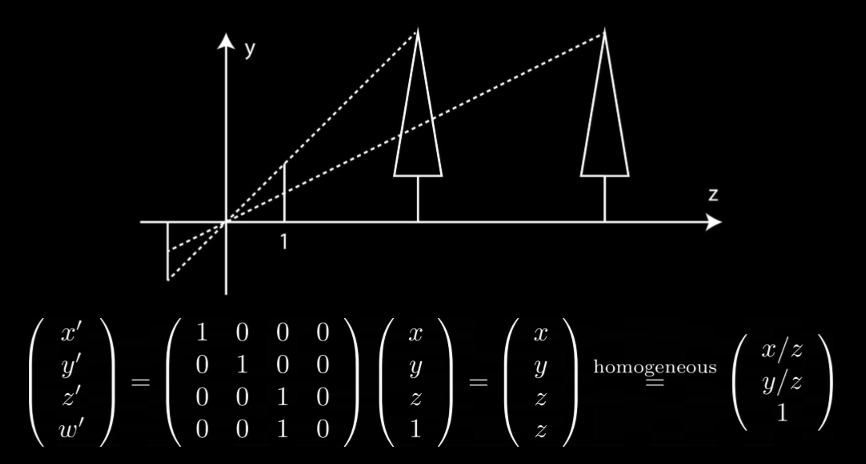
The projection plane is at z = 1, and has a height of 1. The first tree is at z = 10 and has a height of y = 10. On the projection plane, the tree would have a height of 10 / 10, or 1, on the projection plane. The second tree also has a height of y = 10, but it has a distance of z = 20. Therefore this tree would have a height of 10 / 20, or 0.5, on the projection plane. For culling purposes, we store the depth as a quantized z-value before calculating the perspective division.
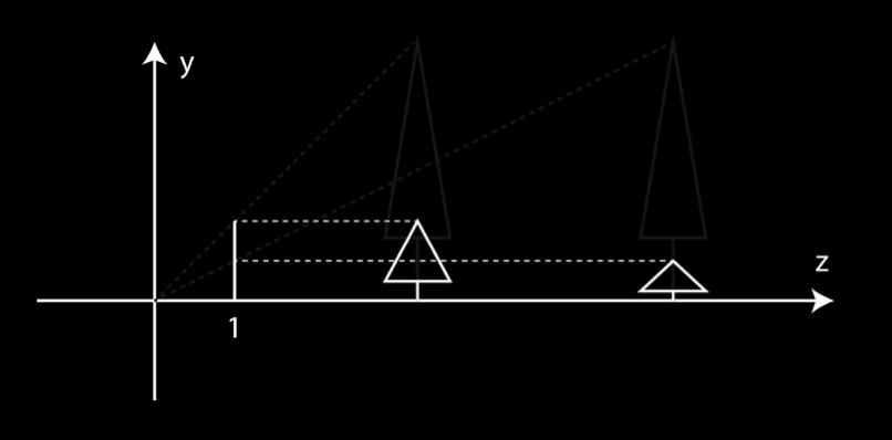
In WebGL, this frustum perspective calculation is done using mat4.frustum(). It uses the above concept with additional parameters that define the left, right, top, bottom, near, and far clipping planes for the projection. This gives precise control over the view frustum’s boundaries.
Another option for calculating perspective projection is using mat4.perspective(). This uses the camera’s fovy (basically field of view) and the aspect (width / height of the projection plane). This only needs two clipping planes: near and far.

Combining all the matrices
There are multiple valid ways to combine the projection, view, and model matrices.
- PVM (model-view-projection matrix) is generally the best as it combines all 3 transformations.
- P and VM (model-view matrix) and P, V, M are also valid depending on the specific use case (e.g. computing lighting).
All matrix calculations in the program are calculated ahead of time before being sent to WebGL.
Lighting
Info
- Support for ambient, diffuse, and specular lighting.
- Phong shading is used for realistic lighting effects.
WebGL uses OpenGL’s reduced lighting model to simulate the interaction of light with surface points to determine color and brightness. In general, illumination is computed at each vertex then interpolated across the set of points within the triangle being illuminated. This illumination model usually considers:
- Light Attributes such as intensity, color, position, direction, and shape.
- Object Surface Attributes such as color, reflectivity, transparency, etc.
- Object Orientation to determine interaction between lights and objects.
- Camera Viewing Direction to determine interaction between objects and the camera.
The program only utilizes Local Illumination that only considers the light, the camera position, and the object’s material properties. The other illumination model, Global Illumination, is not used. It takes into account the interaction of light from all surfaces in the scene (e.g. ray tracing) and is extremely expensive to compute.
Basic Light Sources and Illumination
There are 3 basic light source types that can be used:
- Point Lights which omit light rays in all directions.
- Directional Lights which omit light rays in one direction across a plane.
- Spot Lights which emit light in a cone.
There are also 3 basic types of local illumination:
- Ambient Lighting is the background light in a scene. All objects in a scene recieve an equal amount of ambient light.
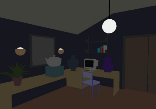
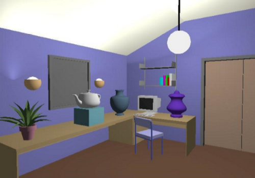
- Diffuse Lighting is the illumination that a surface receives from a light source and reflects equally in all directions. It looks the same no matter where the camera is. It is calculated using the angle between the light source and the normal of the surface normal of the vertex.
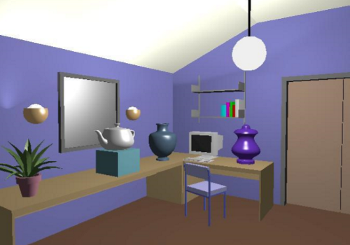
- Specular Lighting creates bright hot spots on an object. The intensity of the specular highlights depends on where the camera is. The closer the camera is to the mirrored angle of the light across the vertex’s surface normal, the more intense the hot spot is.
The total illumination of a vertex is the sum of ambient + diffuse + specular
Shading Models
Flat Shading computes lighting once per polygon. The entire polygon has the same illumination. This makes it very cheap to compute.
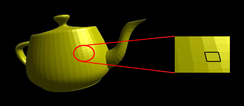
Due to the mach band effect, flat shading is usually only used when the polygons are small enough, the light source is far away, or the camera is far away.
Smooth Shading can remove the mach band effect by interpolating the shading across the polygon. There are two types:
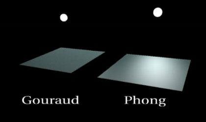
- Gouraud shading calculates lighting on a per-vertex basis. It utilizes the normal of each vertex (can be calculated by averaging the normals of the connected polygons together). Once the vertex illumination values are found, it interpolates them across the area of the polygon. The main downside of this shading technique is the lighting in the polygon’s interior can be inaccurate, leading to poor specular highlights.
- Phong shading is more accurate and provides better specular highlights. The algorithm interpolates the normals of the vectors across the polygon, rather than the illumination of the vectors. This provides more accurate per-pixel illumination and a smooth transition in shading across the entire polygon. The main downside of this shading technique is it is expensive to compute.
Texture Mapping
Info
- Support for applying 2D textures on 3D objects.
WebGL utilizes bitmap (pixel map) textures when rendering. Bitmaps represent a 2D image as an array with each pixel (or texel) having a unique pair of normalized texture coordinates (coordinates from 0 to 1 representing relative position). When texture mapping pixels during rasterization, the texture coordinates are interpolated based on the object’s corners’ texture coordinates. This is done because the specific color required may not align exactly with a single texture coordinate.
To apply textures onto 3D objects, a temporary mapping between 3D and an intermediate surface is made. Then, textures can be mapped onto the intermediate surface with parallel or perspective projection. The intermediate surface can be a plane, cylinder, sphere, cube, etc. Using surfaces such as these make it easier to map 2D textures onto complex 3D geometry by simplifying the coordinate system of the shape.
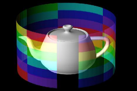
In the program, texture coordinates are included with textured geometry’s data. The textured Ray Gun is imported through a JSON file which contains information about the object’s vertices, texture coordinates, and material properties.
Cube and Environment Mapping
Info
- Support for skyboxes.
- Support for real-time reflections on 3D objects.
The skybox in the program’s scene is created through the use of a cube map. Cube maps are created by placing a camera in the center of an environment and projecting it onto 6 sides of a cube. Then, the scene being rendered is placed inside of a cube with each of its faces displaying one of the images from the cube map.
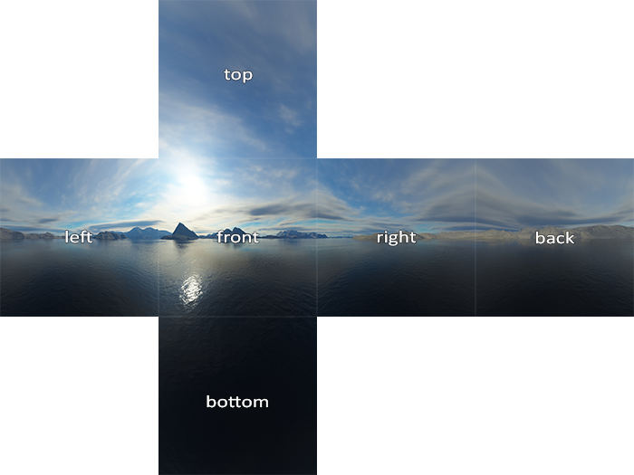
Environment mapping (reflection mapping) is a cheap way to create reflections on curved surfaces by mapping the reflection to the object as a texture. Environment mapping works under the assumption that the environment is far away and the object does not reflect itself. This way, the reflection at any given point can be calculated just by using the reflection vector.
The reflection vector is computed based on the camera position and the surface normal of any given point on an object. The reflection vector is then used to compute an index on the environment texture, and the corresponding texel is used to color the pixel. To find the reflection vector, the following equation is used:
Once the reflection vector (x, y, z) is found, the major component with the largest magnitude is used to determine the plane of the cube map that will be used to find the reflection. Then, the other two components are normalized between 0 and 1 to be used to lookup the corresponding texel. A reflective sphere can be seen in the live demo behind the camera.